Project: Little: Power Section
Role: Developer
Overview#
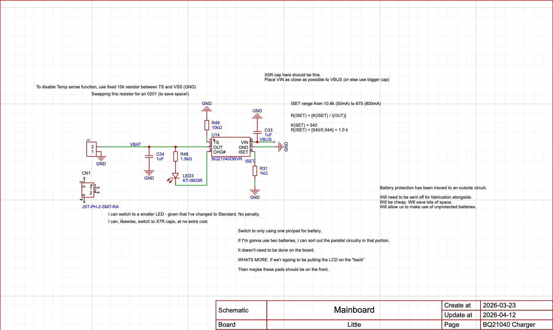
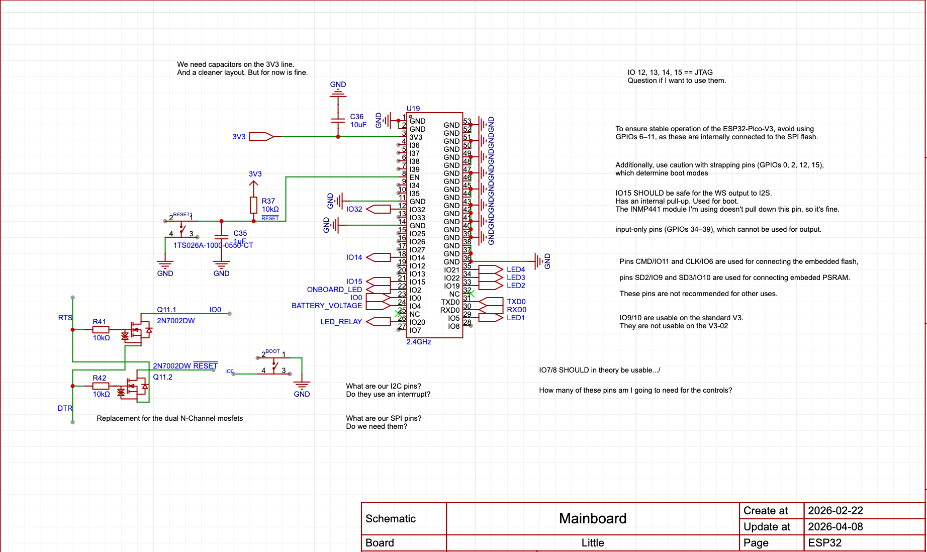
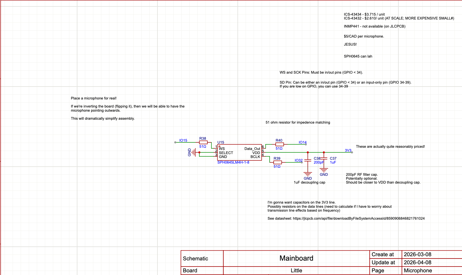
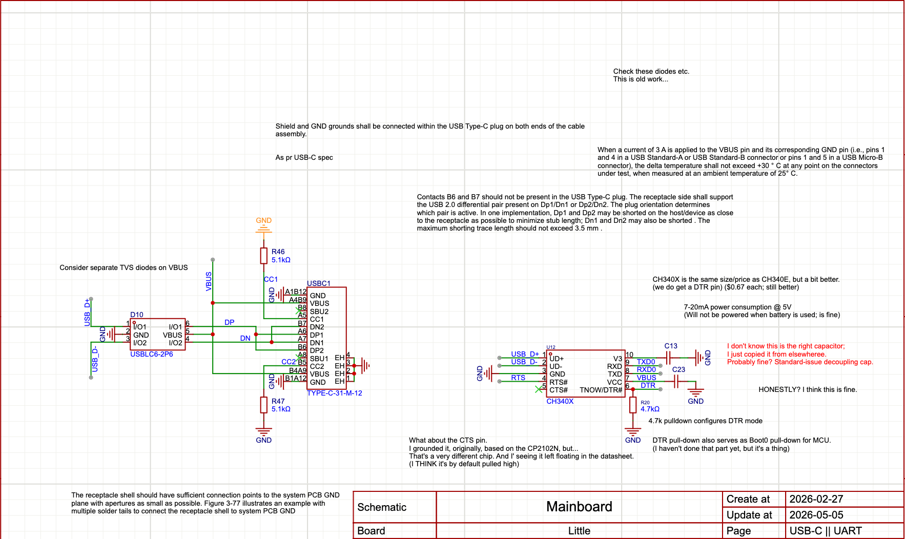
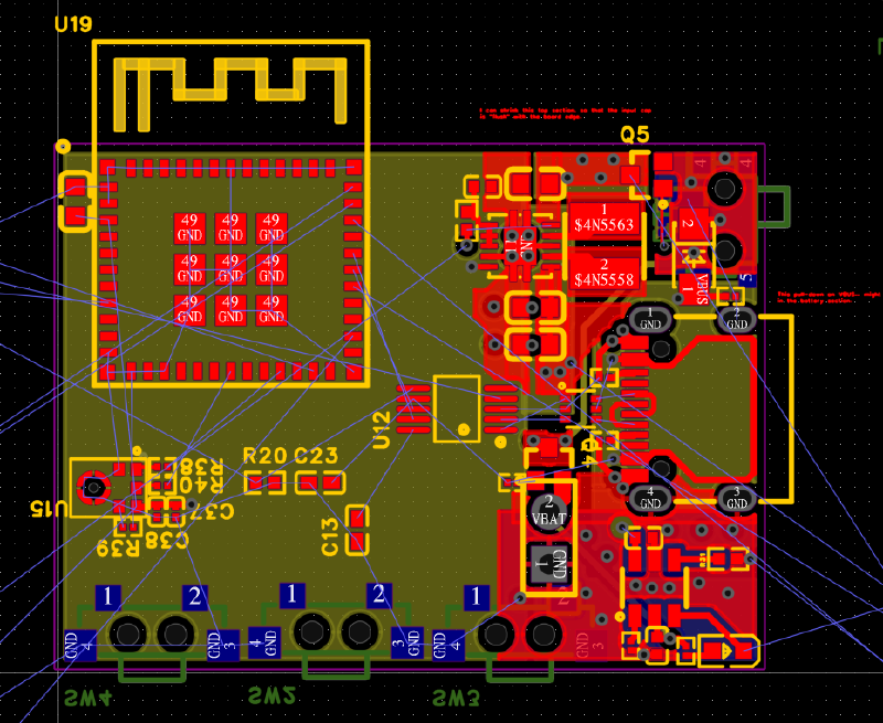
Little is a custom ESP32-based PCB designed for a wearable LED project, with an intended battery capacity of 600-1200 mAh. The Power Section includes a BQ21040 Li-Ion charger, TPS63001 switching regulator, USB-C port with pass-through diode and USB2 data lines, as well as an I2S microphone and control system. Due to the high density of thermally active components and the space-limited form factor, the design limits charge and discharge current individually to 600 mA.
Challenges and Objectives#
- Miniaturization: Achieve a target footprint of 1.35 x 1.00 inch (1350 x 1000 mil), against a physical floor set by thermal dissipation rather than component dimensions — past a point, smaller parts did not yield a smaller board.
- Thermal Management: Limit heat dissipation at the point where the charger’s internal linear regulator and the USB passthrough diode both operate maximally — a depleted battery charging at 600 mA while the system draws another 600 mA through the passthrough.
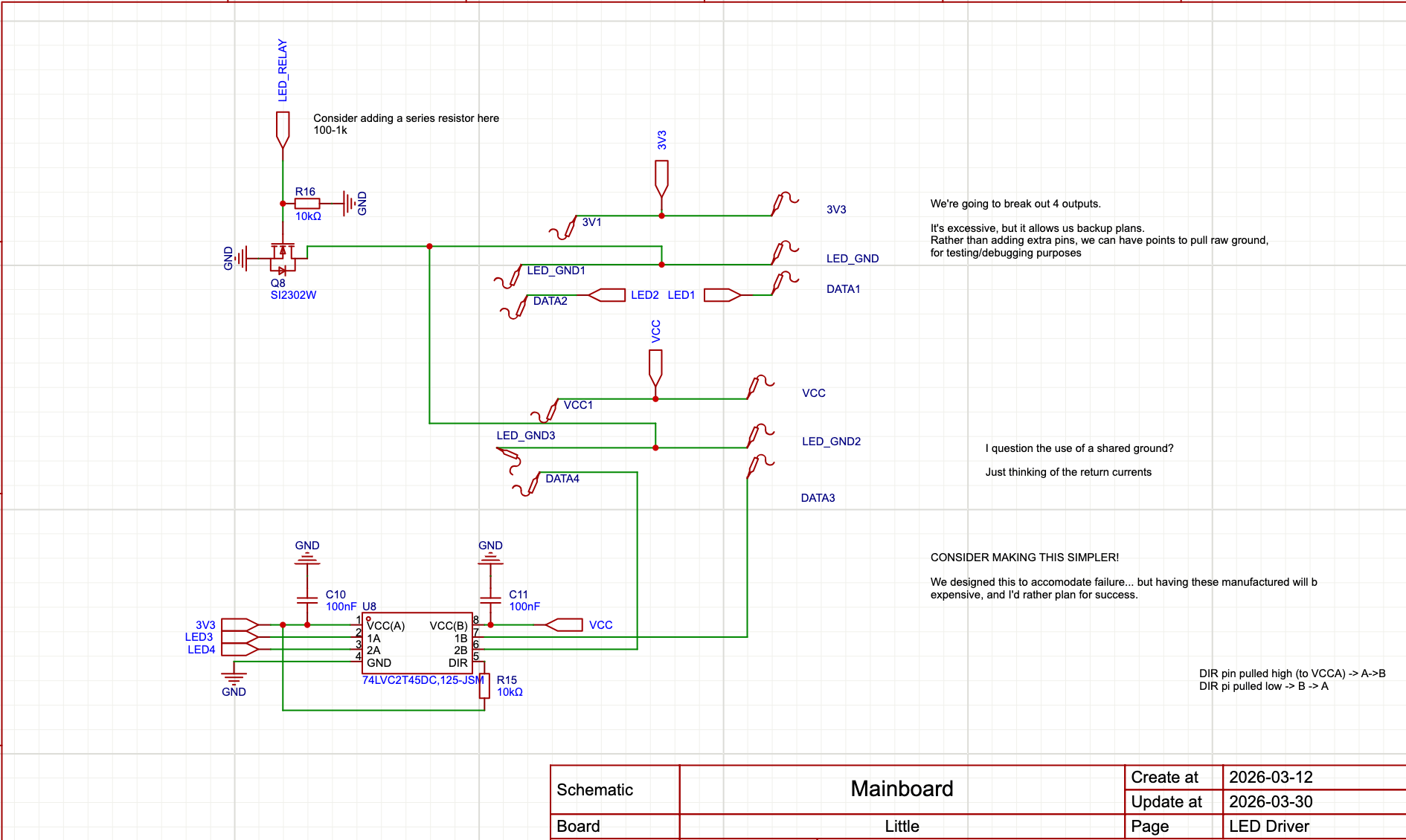
- Power Efficiency: Supply an ESP32 alongside 24 SK6812 LEDs from a 600-1200 mAh battery, while keeping system draw under 600 mA. The LED load uncapped would far exceed that ceiling, requiring firmware-level brightness caps.
- Noise / Signal Integrity: Contain switching noise from the 3V3 regulator — a deliberate trade-off against a linear alternative — and provide a fallback to drive the LEDs from VSYS if the regulator cannot stabilize under the system load.
- Engineering Rigor: Meeting the thermal, layout, and signal-integrity constraints required study of the underlying principles and a subsequent redesign of the board.
- Cost & Manufacturing: Miniaturization pushed the design towards progressively finer pitches, and each step up in assembly capability added cost. The current design sits at that crux — the 0201s and Pico require machine assembly, but the backside switches and LCD can be mounted by hand, trading labour for a lower assembly bill.
My Contributions#
1. Form Factor and Reuse#
- Form factor traced from the original cat ears; outline laid out for LED placement and 3D printable shell production.
- Double-sided SK6812 RGBW PCBs repurposed from prior work; third-party dev boards used as reference for footprint and layout constraints.
- Harvested disposable vape batteries (600 mAh 12650), chosen due to accessibility and weight, with option to parallel for higher capacity.
2. Power Architecture#
- Made use of the BQ21040 linear charging IC over the TP4056 and TP4054, prioritizing footprint over peak charge current and accepting a linear topography over a noisier switching alternative.
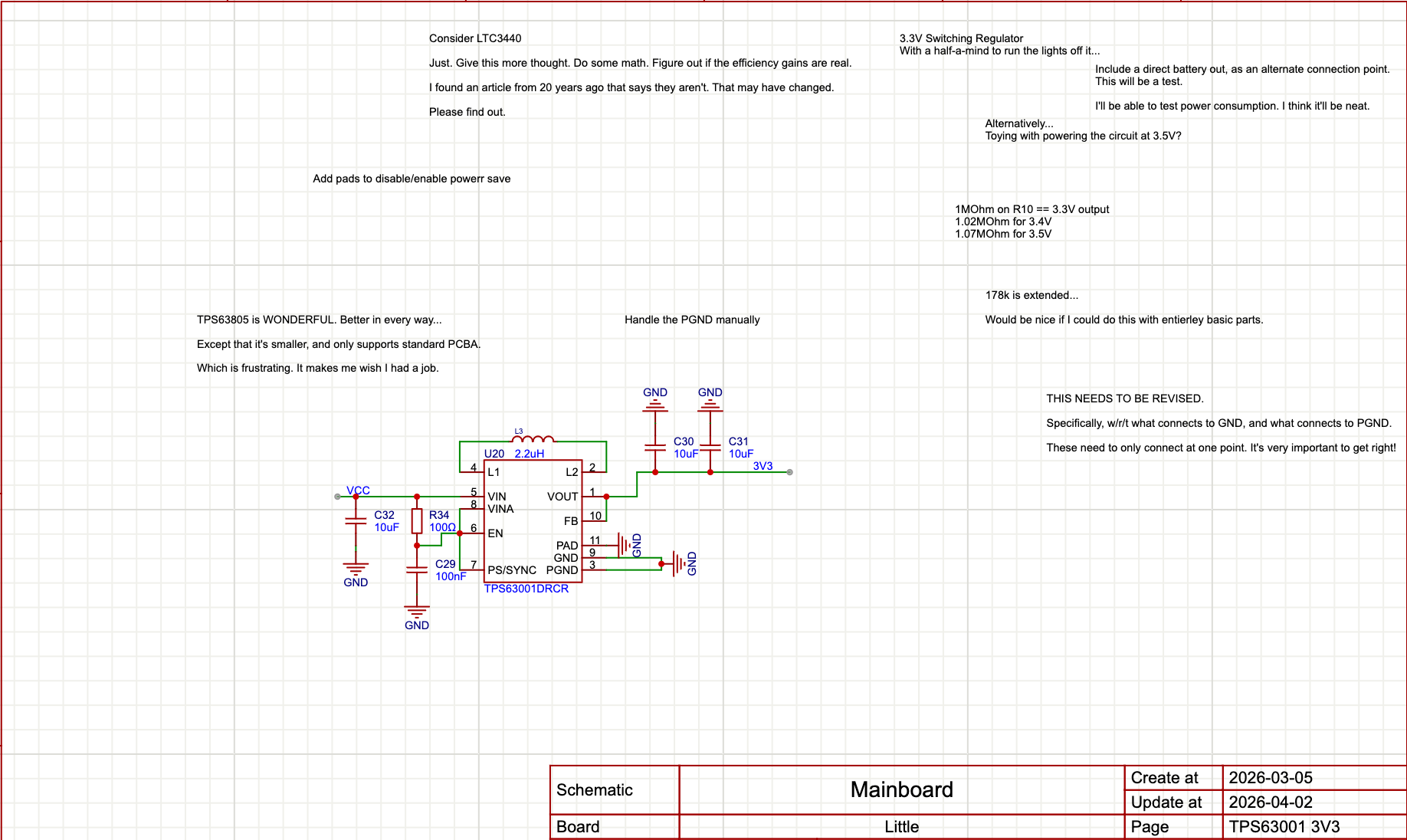
- Adopted a TPS63001 3V3 switching regulator for the MCU and LEDs, betting on extended runtime as battery capacity falls — the regulator holds 3.3V where VSYS would sag. The VSYS fallback covers noise stability as well as LED function, since the 5V-rated LEDs are deliberately undervolted to 3.3V for efficiency.
- Used P-channel MOSFETs as relays for the LED circuit, the power switch, and the USB pass-tthrough, switching the LEDs off when idle to offset their ~1mA quiscient draw.
- Designed a separate protection board around the XB8089 to cut discharge below 2.9V — essential for the switching regulator configuration, since the harvested cells are unprotected, and vulnerable to over-discharge.
3. Thermal Engineering#
- Identified two dominant heat sources — the BQ21040’s internal linear regulator and the USB pass through diode, whose worst-case operation coincides.
- Redesigned around a 600 mA per-section limit, set by the point where a depleted battery charging at 600 mA overlaps with the system drawing another 600 mA through the pass-through. Exceeding it triggers thermal throttling of the charger, which fails sae.
- Swapped the pass-through diode for a part with better thermal characteristics and lower voltage drop; confirmed the 3V3 switching regulator contributes minimally to thermal load.
4. Layout and Manufacturing#
- Miniaturization forced a move from Economic to Standard assembly ($8 -> $25) to access 0201 components and the smaller BQ21040 package, as well as mounting the ESP32 module.
- Settled on the ESP32 Pico over other modular and SMD variants — opting for ease of FCC certification and avoidance of the need to design my own antenna.
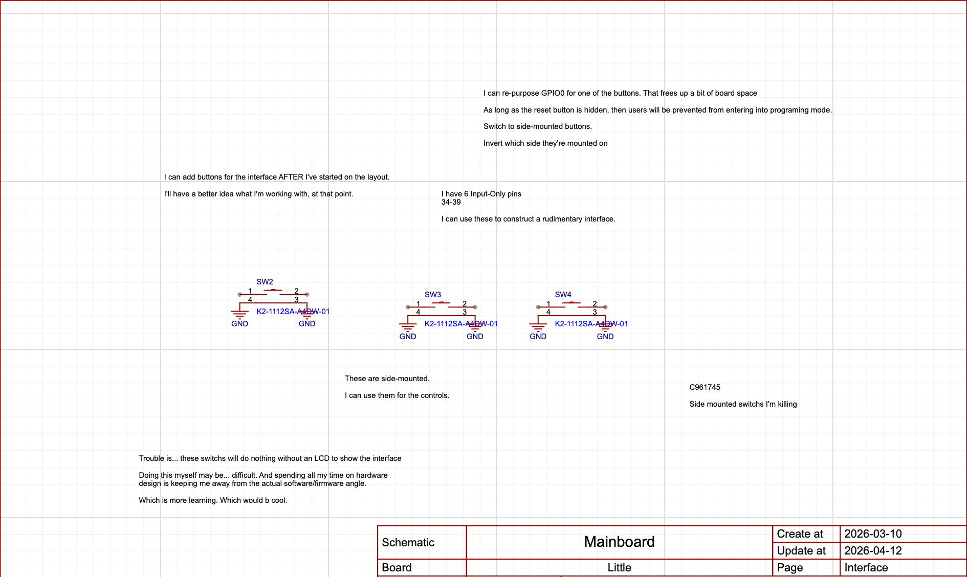
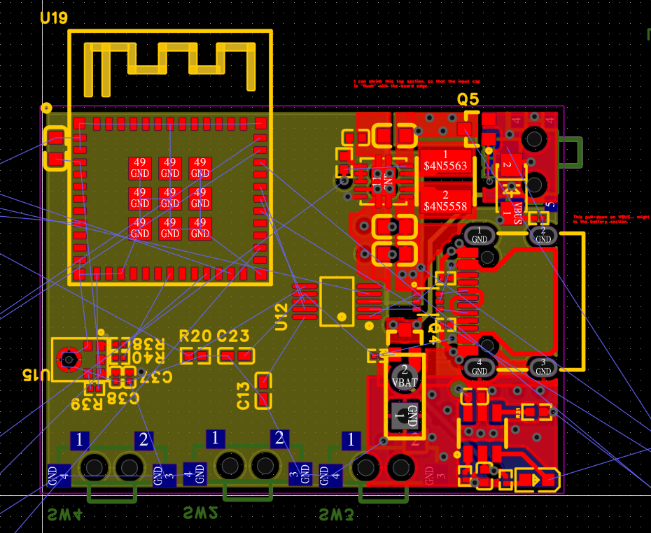
- Relegated user-facing switches and LCD ribbon connectors to the reverse side, enabling hand-finishing to avoid a move to double-sided assembly ($50).
- Segmented the board by section, routing signals to avoid crossing the noisy ground of the regulator/inductor circuits.
5. Future Improvements#
- Explore using PCB material as the superstructure — a white FR4 board with markings for each LED mount, potentially cheaper than individual 3D prints, and less brittle than oxide-tinted white filament. Light would reflect off the underside back towards the viewer, and it would be vastly easier to manufacture.
- Finish the design to a manufacturable state: finalize the BOM and form factor, and obtain a quote for a small run.
- Explore the use of wire as a part of the superstructure. The original design used a flat piece of wire as the headpiece, and it provided the correct degree of spring to survive use (which an entirely 3D printed design might not obtain).
Outcomes and Results#
- Completed Power Section: Schematic, layout, and component selection for the charging, regulation, protection, and switching circuits — the foundation for the MCU and IO work to follow.
- Defined Thermal Envelope: 600 mA per-section limit established, with fail-safe throttling of the charger under worst-case concurrent load.
- Miniaturization Within a Thermal Floor: Footprint target met, bounded by heat dissipation rather than component dimensions.
- Assembly Strategy: Standard-tier assembly for 0201 components and the Pico, with hand-finishing of backside switches to avoid double-sided cost.
Reflection#
Little was born in much the same way as the original hat did — with an object so charming I felt the need to recreate it almost entirely, improving every facet beyond recognition. What’s different is scale — aand what stood in the way of it. The hats were always intended to evolve towards mass-production, but each was labour-intensive to assemble. Little demanded a higher-degree of minaturization, which pushed the manufacturing problem down to the level of the board.
This was my first power system designed from scratch. Every prior prject had leaned heavily on modules — a charging board, a switching regulator, a microphone, and dev boards that came with included voltage regulation, and serial communications. Here, those problems became the scope of work, and I ran into real, physical limitations. To verify the design, I read High Speed Digital Design and the Printed Circuits Handbook, and through that study came to understand the flaws in what I’d drawn — enough to rework it into something I can look at and consider safe.
The result is the power section: charging, regulation, protection, switching. It’s complete, and ready to be integrated into a greater whole. The MCU and IO work remains, however the foundation is sound, and the thermal envelope is well defined. Worst case operation triggers fail-safe throttling rather than failure, and each part of the design, at minimum, will produce useful data for whatever comes next.
Technical Summary#
- Skills: PCB Design, Electrical Engineering, Power System Design, Thermal Analysis
- Tools & Components:
- MCU: ESP32 Pico
- Charging: BQ21040
- Regulation: TPS63001 (3V3 Switching)
- Battery Protection: XB8089
- Audio: SPH0645 I2S Microphone
- Connector: USB-C
- LEDs: 24x SK6812 RGBW (double-sided, 6 boards per ear)
- Battery: 1-2x 12650 Li-Ion (600 mAh each)
- Key Features: Space-constrained layout, undervolted LED drive for efficiency, fail-safe thermal throttling, battery charging and protection, USB pass-through.
Gallery#